CIRCUIT SCHEMATICS:
E- 128 pin out

Battery management
All motors are directly connected to the battery to eliminate noise. Since the motors are directly connected to the battery, the shared impedence is reduced which in turn reduces noise. All batteries' grounds are connected together. A 3 V battery is used to power the launcher motors. 5 V voltage input for the sensor, emitter and LED circuits is obtained by using a 7805 voltage regulator for which the input voltage is 7.3 V from the battery. The driver motor and servo motor is powered by another 7.3 V battery. 7805 is used on servo motor circuit to power the servo with 5V.
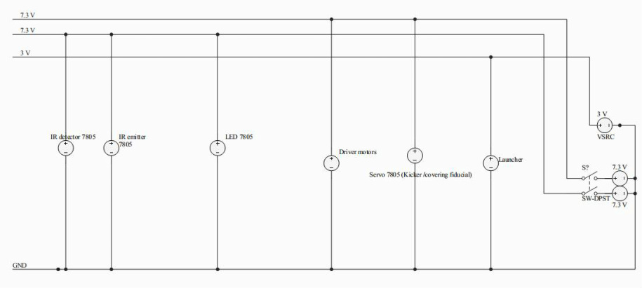
Photo transistor
A hysteresis band of +/- 0.2 V is used. The resistor values at the comparator stage are chosen to achieve said hysteresis band.

IR emitter circuit
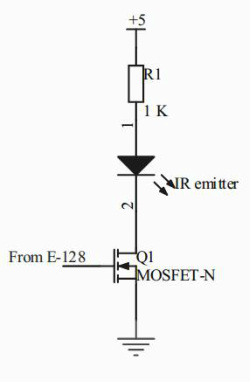
The IR emitter is switched by the MOSFET using the E-128.
Motor H-bridge circuit

The driver motors are operated in drive brake mode.The PWM input is given from the E-128. Diodes are used to protect the transistors in the H bridge from large inductive voltages.
7805 sample circuit
A 7805 is used to regulate the voltage to 5 V from 7.3 V input voltage for circuits which require 5 V input voltage.

Launcher circuit
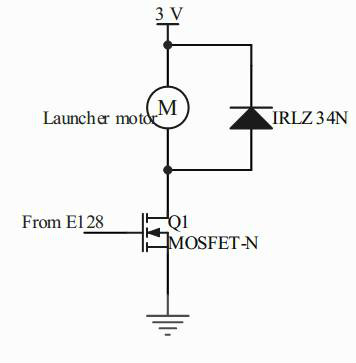
PWM is applied to the MOSFET to control the speed of the launcher motor. A protection diode protects the MOSFET from large voltages generated due to the motor inductance.
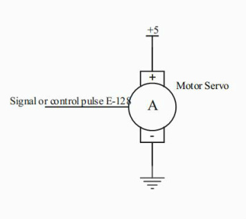
Servo circuit
The control pulse for the servo circuit is given from the E-128.
LED circuit
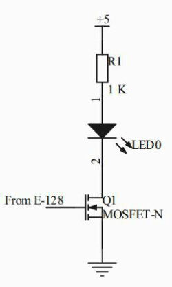
The LED is used to indicate the game status.
It is switched on or off with the MOSFET using the E-128.
It is switched on or off with the MOSFET using the E-128.
